The USS Enterprise (Refit) from Star Trek: The Motion Picture

Build Log – Part 9

All righty!  More work on the engine nacelles – and their internal wiring.

First off I want to sing the praises of that Vallejo surface primer again – it’s been really excellent to work with.  Dries extremely smooth, lays flat, and is rather forgiving of when I “overdo” it.  I highly recommend it.  I used a lot of it on these parts, and will probably need to get another can or two soon.

The Lights

On to the wiring.  I first established how many and what kinds of lights needed using:

LED tape – two strips for each engine, in blue.  I thought about going violet (the studio model was actually done up in violet), but I’m aiming to replicate what we saw on-screen, and those are distinctly blue.  Each strip is about 20cm long, and I’ll fix them with staggered lighting so I avoid the worst of the “stepped” lights.

LED tape cut and ready, with styrene diffusers.

LED tape cut and ready, with styrene diffusers.

Blue LEDs – two, one for each “warp crystal” at the top of each nacelle.

3mm white LEDs – four.  Two for each nacelle, one to each side, for use in the Raytheon floodlamp effects.

2mm white “tower” LEDs – four.  One for each of the two spotlight ports at the front of each nacelle.

2mm yellow LED – two, one for each thruster section in the fins.

SMD white LEDs – two.  One for each of the anticollision strobes on the rear roof of the nacelles.

With the exception of the tapes, each of these LEDs required a resistor…and since I’m aiming to make this a 9-volt setup, a 470 ohm did the job.

A word about resistors and LEDs – when they ship from the factory, the standard for LEDs is to have one leg shorter than the other.  That’s the “cathode”, or negatively charged lead.  The positive is referred to as the “anode”, and all LEDs are polarized this way…they only work if you connect the correct leads to the correct charge.    For bare, unwired LEDs, the resistor attaches to the cathode, the shorter arm.

In my models, I use a lot of “magnet wire,” which is extremely thin (36 gauge or smaller) and insulated using a laquer coating rather than a plastic sheath.  Some of it comes colored from the factory in a variety of different shades, and although I do use those sometimes, I tend to stick with this stuff which is really really fine (thinner than a hair), and that stuff doesn’t have color.  It’s just bare copper (insulated with laquer).  It’s a little fragile and sometimes can be hard to work with, but I find that it fits into the smallest little spaces and doesn’t “spring back” like a lot of other wires can, so the pros outweigh the cons a little for me.

An LED with resistor already attached, note the winding of the magnet wire

An LED with resistor already attached, note the winding of the magnet wire

Under normal circumstances, the wires to be connected can be held together and solder applied, which then works both as an electrical connection as well as a “glue” – but with magnet wire, it’s so thin that you just can’t hold it steadily in place and convince solder to stick it properly.  It’s also so thin that it doesn’t accept ‘tinning’ like regular wire or cable does.

In my previous logs I’ve mentioned this, but it does bear repeating, so forgive me for my redundancy.  To get magnet wire to behave, first you have to get the laquer insulation off the ends.  To accomplish this, the best way I have so far (and this is different from before) is to take some 600+ grit sandpaper, fold it in half, and then pull the section of wire you want to strip through the folded paper while applying gentle pressure.  Too much and you’ll just break the wire, too little and you won’t pull any laquer off.  You’ll figure it out after a few tries.  Once you’ve done this a few times, you can then run a hot iron over the cleaned section to burn off any remnant laquer.

I trimmed down the arms and the ends of the resistors to avoid extra-long connectors, and tinned the ends of each.

Example of the wiring harness for the LEDs - I also insulated the connections with masking fluid and black acrylic paint.

Example of the wiring harness for the LEDs – I also insulated the connections with masking fluid and black acrylic paint.

Since these LEDs have lots of breathing space inside the nacelles, and since I’ll be wiring them all up in parallel, I connected the resistors directly to the short arms.  (Had I been using series circuits, I would only need one resistor for an entire string of LEDs, but I don’t want one burnout or short to result in a “Christmas tree outage.”)  I then connected a short (5-10cm) length of magnet wire to each, and then a longer (25cm) length of plastic-sheathed cable colored in black and white for polarity.

Negative should always be black, by the way.

To connect the magnet wire to the heavier leads and wires, I physically wrapped the magnet wire around the subject four or five times so that it would hold itself in place without me touching it.  Once this was done, I could then go to town with the soldering iron and some clean solder – once the wires heat up properly, the solder’s surface tension pulls amounts of it into the twined magnet wire, resulting in a really good connection and a very strong solder point, with the added benefit of remaining very thin and easy to work with.

Using a 9V battery I ran tests of the harnesses almost every time I handled them, just because I'm paranoid about breaking connections.

Using a 9V battery I ran tests of the harnesses almost every time I handled them, just because I’m paranoid about breaking connections.

Lastly, in order to avoid shorts inside the model, I applied a latex coating to each soldered connection and painted them with an acrylic paint.  This completed the wiring harnesses and provided their exposed wires some extra insulation against shorts.

The Inner / Outer Grilles

After getting all the lights ready, I set them aside and started masking up the inner grilles for painting.  These two parts are completely clear in the kit.  The portion which is internal to the engine I left masked off initially to avoid getting it contaminated with the paint I was using on the exterior.

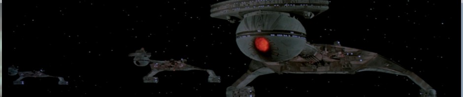
These parts pose a rather interesting challenge – they have a series of raised ridges and “trenches” between them, and the only section that is supposed to transmit light is a portion of the “trenches”.  These gaps are only about a millimeter wide, but they are about 20cm long…and the lit portion is about 15cm-17cm long, gently differing at the rear to produce a “curved” look to the lighting.  See the reference photo and look at where the blue light in the engine grille is coming from to see what I mean.

Originally I wanted to use some very thin plastic masking tape in 1.6mm width, but when I tried this, the edges protruded in a really unwieldy fashion.  After a half hour of frustration working this way, I gave up on the skinny masking tape and switched to a liquid masking solution from Humbrol called “Maskol”.  This is a liquid product that dries into a rubbery latex that is easy to pull off a surface.  Brushing it directly into the trenches was not a good option, as bleed over to the tops of the grilles wouldn’t come free without dragging a chunk of the mask out of the trench as well.

The grilles before painting

The grilles before painting

In the end I used a 1mm syringe needle to inject the stuff into the trenches where it needed to go, and this worked out fantastically.  (If you have any diabetic friends, or know a veterinarian or doctor, you can probably arrange to get a couple of these from them, so long as you aren’t a likely candidate to be using injectable drugs.)  However, I tried to clean the syringe using warm water, and that

After painting the grilles

After painting the grilles

caused the latex to set…inside the needle.  So, scratch one good syringe needle.

Once the mask was on, I sprayed the parts with Army Painter Matte Black primer, which gave me a nice clean black finish.  Some folks go for a deep violet almost indistinguishable from black (which is more studio accurate), but looking at it from a meter away with the lighting up, I don’t think there’ll be anything notably different.  I also hand-painted the grilles on the collector parts that go into the front of the engines.

I have noticed since then that the grilles are a little bit transparent on the painted sections still, so I might have to go back and apply another coat of black on them if they look bad when the lights are on.

Using masking tape, I then set out to mask off most of the external nacelle surfaces, leaving only the outer grilles available for view, and sprayed those up nicely too.  A little hand-painting of the spots missed, and cleanup around the edges, and problem solved.

The Fins

At the rear of each nacelle is a horizontal and a vertical fin.  The vertical was painted in a ‘duck egg blue’ for the film, so I went ahead in advance and painted it appropriately.  It’s worth noting that duck-egg blue is a very light color that can be easily transparent if it isn’t thin enough, and it needs two coats at least if you are using a regular brush.  I think with an airbrush this would be a little different.

Horizontal fin, wired up - notice the broken magnet wire. Easy to fix, but this is why I'm always checking my lights.

Horizontal fin, wired up – notice the broken magnet wire. Easy to fix, but this is why I’m always checking my lights.

The horizontal fin will house a thruster lamp, so after positioning the LEDs in the right spots, I then glued them in place.  I sealed up the fins and puttied the cracks (which were rather pronounced), and after sanding re-whited the fins.  One of them needed a little more sanding after the white was reapplied, and a little more putty to fill in the gaps.  Just to be sure, once this was done I re-masked the thruster section and did a second black light-block on the remainder before reapplying white.  I also drilled a 3mm hole in the section of the nacelle where the fin would mount, so the wiring would have an escape route.

Black Seal. No animals were harmed in the making of this product. I hope.

Black Seal. No animals were harmed in the making of this product. I hope.

Note that when handling these parts with magnet wire attached, you do have to be very careful not to bend or pull the wires quickly – always be gentle.  I made one error (happy to say it was easily recoverable, see image above), and snapped the wire off the resistor.  Really easy to do if you aren’t paying a little attention to it.

Once these were done, I wanted to make sure that no light leakage from the thruster made it into the main body of the engine (because when the warp lights are off, those interior grilles are still clear and need to avoid having bleed-through).  I also wanted to practice with a new product I’m using on this model – “Black Seal”.  It’s a silicon gel that hardens up into a stiff material, completely black in color, so it makes a great gap-filler for spaces that need to block light.  I pushed a little of this into the fin so as to get zero light bleed from the yellow thruster light.

A few dabs of Black Seal on a toothpick fit right in.

A few dabs of Black Seal on a toothpick fit right in.

Working with Black Seal, it is almost inevitable that you will get some on your hands, and as a result you will probably leave a smear on the model exterior parts.  Don’t panic.  This stuff wipes right off with a paper towel, and even after it cures it is just silicon – it should rub right off.  I had more than my share of black smears on my engines here before this was done, and they all came off without a hitch.

The Warp Strips and Crystal

At the nose end of each nacelle, on the top, there is a circular clear part that is supposed to

LED glued onto the warp crystal - using an under-prop and 'helping hands' to hold it while it dries.

LED glued onto the warp crystal – using an under-prop and ‘helping hands’ to hold it while it dries.

glow blue when the warp drive is engaged.  After I retrieved each of these parts, I drilled into them with a 2mm drill bit from the bottom, and glued the blue LED to each one.  Once the glue was dry, I hit the outside of them each with some silver paint, and then black to prevent leakage.  These LEDs were then connected to the same leads as the LED tape, since they’ll all power on simultaneously.

The strips each got a lead, and I cut some clear styrene sheet to act as a diffusion cover, which was sprayed with dull coat to give it a frosted appearance.  Once I fix the strips in place, I’ll cover them with this to further avoid ‘hot spots’ showing from the outside.

In addition, it’s worth pointing out that the external grille has a small window at the front which is intended to light up along with the warp drive.  To help direct some of the right light to it, I cut a couple of styrene strips and painted them silver to act as a mirror effect from the blue strips, then mounted them ahead of the windows with a severe angle to direct light out the little windows.

Exterior grille light window with styrene reflectors in place.

Exterior grille light window with styrene reflectors in place.

Forward Floodlights

Each of the forward floods is going to receive a tower LED, and unfortunately the sections that will receive these LEDs are only light-blocked from the interior…which means that the tower sections may cause some bleed-through of their light if I’m not careful.  To avoid this, I painted each tower black all over except the emitter end.

"Tower" style LEDs, painted silver and then black over the entire surface except for the light-emitting top of the tower.

“Tower” style LEDs, painted silver and then black over the entire surface except for the light-emitting top of the tower.

Anticollision Strobes

Each of the four halves has a round port that will accept the plastic part, but we're putting an SMD in here, so it needed to be enlarged a little to fit.

Each of the four halves has a round port that will accept the plastic part, but we’re putting an SMD in here, so it needed to be enlarged a little to fit.

The section at the rear of the engine for the anticollision strobes are very small ports designed for a clear part to be added here.  This port is smaller than the SMD lighting that I’ll be using to provide the electrical effects, so each one had to be widened out a bit to fit.  Once they were opened up, I fitted the SMDs to the interior half of the nacelles and glued them in place using canopy glue.

For all of these lighting harnesses, Once the lights are fixed in their places, I’ll then glue the wiring in place in several places using CA and hot glue, bringing the leads all to the connector site where the nacelles mount on their pylons.  I also use a bit of masking tape at the ends of their leads to keep the appropriate leads together and to give me a place to label them so I’ll know which is which.

Close-up of the SMD mounted in place.

Close-up of the SMD mounted in place.

SMD mounted - note masking tape holding the wiring steady to avoid accidentally pulling the chip free.

SMD mounted – note masking tape holding the wiring steady to avoid accidentally pulling the chip free.


Lastly, for all of these lights, I secured the wiring inside the nacelles with masking tape until I glue them in place (which I’ll show in the next installment).  Additionally, I used masking tape to secure the positive and negative leads for each light harness separately, and labeled each one so they wouldn’t get confused.  Once this thing is sealed up, if I get those wires confused, the only way to check them is to do a process-of-elimination test with each one to see what lights up with what wires.  Don’t want that hassle, so on go the names.

The proverbial 'ounce of prevention' here.

The proverbial ‘ounce of prevention’ here.


USS Enterprise – Build Log Part 10USS Enterprise – Build Log Part 8

Posted in Build Log, Model Kits, Sci-Fi, Uncategorized | Tagged , , , | 2 Comments

A Quick Break from the Enterprise

Shame.  Shame.  Shame.

In a particular moment where Trump and Cruz are dominating the news about the GOP, I want to call attention to Lindsey Graham. Not because of anything special about him, no, but specifically because of something very mundane about him:

Even though he hates Ted Cruz, he still supports him against Donald Trump.

Now this strange circumstance is what I want to point to – because it’s not unique to him, it’s just that he’s a very visible public face of the malady. Sooooo many people “support” the Republican party. And I have asked this for literally DECADES:

Why? What is in there that appeals to you?

Anything that might have been “grand” in the GOP is dead, people. It’s not like you’re rooting for the Cubbies, who despite having not won a World Series in over a century, still can play baseball pretty damned well. The Republican party, well, it just isn’t. The party is over, people. Today it represents the most un-American, and for that matter inhuman, sides to practically every argument that demands government policy. If we were to scrub off the names and compare it to parties in the 1930s, it would be virtually indistinguishable from the National Socialists.

But we still see people like Lindsey Graham, who for some indecipherable reason can’t let go. It’s like watching people who have been conned for ages continue to phone into their 1-900-psychic hotline, “because they’re my friends, they know me!” Or keep paying money to television preachers, “because God needs my money and HE will see to it that I win the lottery!”

So…faced with the choices in front of him, Graham chooses a man who would very likely be the worst president this country has ever seen. Worse than George W. Bush. Instead of Trump, because of course (borrowing from Bill Maher) while Cruz might be our worst – Trump might be our last.

But what he doesn’t see is that there is another choice, one even more viable and one which would actually SERVE THE BEST INTERESTS OF THE COUNTRY.

Oh my, what choice is that, you ask?

Here it is: DISAVOW the Republican party!

Pretty damned simple, hey??  Believe it or not, it is.  Un-register as a Republican and make it publicly known that you will not stand by any candidate who espouses the vile and repugnant opinions voiced by the current lineup.  Let the world know that you refuse to align yourself with those voices.

But what did he do instead?  He held his nose, aimed his finger to pick, and supported a candidate who would be a terrible blow to our country’s future, our standing in the world, and our people.  A candidate who stands for the most un-Christian values wrapping himself in the mantle of a fanatic sect of Christianity that most who claim the label “Chrisitan” would view as heretical, evil, and ugly.

Look, people, no one is saying you have to line up at the polls to vote for Hillary.  Or that you have to “feel the bern.”

But I, and by collective inference WE, the rest of the American people, are saying that we expect you to be better human beings than this.  And when you continue to either vocally claim the Republican label, or by your silence you do not condemn the Republican party for its slide into evil, we lump you in with them.  You are supporting an evil regime, and you deserve all the shame and repudiation that such support earns you. 

And while we, the rest of the American public, your friends and your family, respect your right to hold your opinions and your views, we do not have to respect you for holding them.

Because when you support such a hideous mockery of not only our people’s country, but of history itself, you don’t deserve respect.  You deserve condemnation and ridicule right alongside the fanatical and evil tyrants that want to become the next President of the United Republican States.

Shame on you.

Posted in Uncategorized | Leave a comment

The USS Enterprise (Refit) from Star Trek: The Motion Picture

Build Log – Part 8

Now we're starting to get some larger pieces

Now we’re starting to get some larger pieces

For the next sub-assembly, I’m going to do the engine nacelles, port and starboard. Not too many parts, but we are starting to stray into an area where the parts are rather large.

For starters, I’ve separated all the pieces from the main bags and sanded / filed them smooth. I’m leaving the clear parts on their sprues for the time being. I’m also re-viewing shots of the ship when at warp as well as at rest, to give myself an idea of what parts of the inner grilles will need to be clear and which will need to be opaque (the part for each grille is entirely clear).

The LED inventory

The LED inventory

Since I’ll be replacing most of the clear parts with LEDs (it’s handy that most LEDs are clear dome-shapes to begin with), I’m going to inventory the lights I’ll need and assign a type for each.

Navigation / anti-collision strobe – this is the blinking light on top of the rear of the engine. I’ll use a white SMD for this.

Forward flood lights – these are at the bottom of the front of the engine, facing the saucer. 2mm white tower-LEDs will work here.

Warp crystal – the blue dome just behind the forward section on the top of the nacelle. I’ll keep the clear part for this, but I will drill it up from beneath and mount a blue LED in here. It’ll be dark under impulse, blue under warp power.

Inner grilles – these are black when under impulse power, and glow blue (remarkably close to Cherenkov radiation in hue) when at warp. I’ll use two strips of blue LED tape in each engine for this.

The yellow needed some pretty severe sanding to get it to fit inside the nacelle fin.

The yellow needed some pretty severe sanding to get it to fit inside the nacelle fin.

Thruster lighting – the yellow rectangular area on the outer fin of each nacelle will also be lit. A small yellow LED will suffice here.

Rear spotlights – the ship name and call letters were lit on the studio model from an external source, in such a way as to make it look like they were receiving illumination from floods on the thruster fins. To replicate this, I’ll use a “Raytheon” style setup, with larger white LEDs inside the nacelles, removing the light blocking around them so their light will shine through the piece, making it look like they’re being lit from outside.

First step for this was to separate all the parts and sand / file them clean, then mask off the areas which would be needed for direct-contact gluing and so on. Masking didn’t have to be precise, but it’s always better to be more thorough where you can. Since most of the clear parts will be replaced by LEDs, I left them on their sprues for now.

Note to the "Army Painter" people - put a clearer designation on the can, instead of just the cap.

Note to the “Army Painter” people – put a clearer designation on the can, instead of just the cap.

Vallejo stuff - first time I'm using it, it's nice!

Vallejo stuff – first time I’m using it, it’s nice!

I then light-blocked the interior of the parts with a matte black, using Army Painter for this – I have had mixed results with AP brand paint, mainly that it doesn’t get along well at all with Citadel satin finishes. I get crinkles like crazy when putting the two together. I wasn’t going to be using those here, so I didn’t spend a lot of worry on it.


You can make out the crinkling on the masks a little here

You can make out the crinkling on the masks a little here

Once the AP Black interior was dry, I primed the insides and outs with Vallejo Surface Primer, flat white. This is my first time using this stuff, and I’m quite impressed so far. It goes on very light, so it’ll take several coats to completely even up the color distribution. It also lies very evenly, and settles fine into detail work, so I’m quite happy with it so far.

I can see that the masks are getting some cracking / crinkling, so I might have some sanding ahead of me when I remove those. For now, the parts will be allowed to rest and cure for 24 hours while I plan out the circuits.

The white primer is sitting really nicely here!

The white primer is sitting really nicely here!

Speaking of which, since I’m going to be doing a “power up” cycle like in the films, this means I’ll have several circuits for the lights which will need to be kept separate. The shuttle bay had the benefit of being entirely dependent on the interior lighting, so it all ties into one set of leads that will connect to the interior window lighting. The engine nacelles are a different story.

I’ll separate them out like so, I think:
1. Front floodlights
2. AC strobe
3. Warp strips and dome crystal
4. Thruster
5. Raytheon floodlamps
#1 and #5 might end up on the same circuit. Not sure, I’ll have to go back and re-watch those sequences to be sure.

Reference shot - notice the blue grilles in the nacelles, and the blue dome on top.

Reference shot – notice the blue grilles in the nacelles, and the blue dome on top.

Tomorrow I’ll connect up my resistors to the LEDs, and add leads to each lamp / strip for both engines, and start fixing lights in their places. Probably will also glue some parts together. I’ll let you know how it goes.


USS Enterprise – Build Log Part 9USS Enterprise – Build Log Part 7

Posted in Build Log, Model Kits, Sci-Fi | Tagged , , , | 2 Comments

The USS Enterprise (Refit) from Star Trek: The Motion Picture

Build Log:  Part 7

All right!  Today we’re going through a few different items – the DLM resin cargo containers / travel pods / work bees, the clear tube columns at the back of the bay, the shuttlecraft, and connecting the fiber optic we built in the last installment.

DLM parts

DLM parts as shipped

DLM parts as shipped

DLM ships their parts in clear and grey resin, depending on whether your part is intended to be lit or not (and most of the parts they offer in clear are avaible in grey if you aren’t lighting your kit).  The mobile units are in grey, which is fine.

First off, decide what you’re going to use and about where you want them. That way you don’t end up making too many.  DLM ships its kit with eight cargo pods, six work bees, and four travel pods – which is really more than you need, unless you intend to do some kind of diorama with a swarm of the little buggers floating all around.  Since I’m only including them in the shuttle bay, I don’t really need that many – I’ll use two bees, one travel pod, and a few cargo boxes on the floor, and I might use a cargo train (in TMP, you get a glimpse of a cargo train arriving, which is basically a work bee with a long attached frame that holds four cargo pods – the Paragrafix PE set includes a piece to make this).

Do NOT remove the units from their sprues yet.  Those sprues make them massively easier to paint.

Paint the units on their sprues so you have something to grip by

Paint the units on their sprues so you have something to grip by

Decide on a hull color for the units.  In TMP the travel pods were something very close to or precisely white.  I stuck with Tamiya fine white primer for those.  The work bees were a light grey in TMP, but I think they look a little better as something like a “hard-hat” yellow, so I went with signal yellow for them.  The shuttlecraft got a base of Tamiya fine white too, after I’d assembled it.


Paint the base color onto the pieces while they are still on the sprue.  Gloss-coat them once dry, and apply the DLM decals there once the gloss coat is dry and cured.  Finally apply a finishing clear-coat to protect the decals.  Once that’s dry, use a fine-tooth modeling saw to separate them from the sprue (leave some sprue attached, don’t get that saw too close to the piece), and file off the excess with a flat-sided file.

Once finished, the bits are ready for PE, or direct installation

Once finished, the bits are ready for PE, or direct installation

PE work-bee arms and cargo train frame

PE work-bee arms and cargo train frame

Here's a sample of the scale you're working with, compared to a standard 9V battery

Here’s a sample of the scale you’re working with, compared to a standard 9V battery

Paragrafix also includes work-bee arm pieces on its PE sheet, which are a bit of a pain to fold properly.  Can be done, but it’s hard if you have big fingers and rough eyes like I do.  Worth it in the end, but not 100% necessary.

Once the pieces are filed to your satisfaction, you can paint their bellies with the appropriate hull color if you think they’ll be visible (mine will sit on the floor of the bay, so I left off the paint – the rough resin surface will actually glue better bare than a painted one, anyhow).

Dry-fit the walls and experiment with where the pieces will look best

Dry-fit the walls and experiment with where the pieces will look best

Dry-fit the bay walls to the floor now, so you get a feel for where everything will be able to

sit.  With the walls attached, position the pieces you want where you want them, and put a small pencil mark there as a reference point.  You can also simply glue them in place now if you feel comfortable doing so (I did).  Carefully remove the walls again once the glue has had a chance to dry.

With the cargo pods, I put on the decals once they were fixed in place, so the showing faces would look right.  The DLM decals are pretty fragile (I think they are inkjet-printed), so you need to be very gentle with them, because the markings can flake off fairly easily.  After the decals were dry, I applied an enamel filter (a very thin wash) that was made as a brown tone for German yellow armor.  This gave the pods a beige tint that fits with what was in the film.  The color scaling works well, and it looks nicer than bare white.  There’s a PE part for the travel pods, but since the one I will use won’t be showing its rear I didn’t use it.  I did attach the decals there, just because it looks neat.

The Shuttlecraft

Assembled shuttlecraft - note the hole in the upper left of the face for a fiber light

Assembled shuttlecraft – note the hole in the upper left of the face for a fiber light

The shuttlecraft, once assembled and base coated, I did a little detailing with miscellaneous colors on the machinery on top.  The base of it got brass along its landing skids (the shuttle you see in TMP brings Spock aboard, and has a nice shot of its lower section showing this too).  A little yellow on the corners for the thruster ports, and a black ring around the docking port.  The rear of the shuttle won’t be visible, so no PE part there and no decals.  I applied decals to the rest of the shuttle, and once they were dry applied a blue filter made for German panzer grey to give it a streaky, metallic look to match what you see in TMP.

Now for a little secret sauce – I used my .5mm drill to poke a hole from the bottom of the shuttle and up out of its “forehead” about where the grey square is on the face of it (top left as you look straight at it).  I also drilled through the floor of the shuttle bay just ahead of the risen elevator.  Remember that extra piece of fiber optic I made?  I’ve attached that to one of the middle lights of the chaser board, and it will be trimmed flush with the face of the shuttle to give it a blinking navigation light.  Shuttle is finished, let’s move on.

Rear Columns

Columns - one with recesses filled, the other blank

Columns – one with recesses filled, the other blank

The rear columns were a real problem for me, because it was hard to see which parts were recessed and needed to remain clear, versus which parts needed painting.  With some magnification (reading glasses) and the light angled just right, I found the recesses and filled them with clear crystal blue paint.  Once that was on, it was a lot easier to see which parts needed regular paint, which I then applied.  The result was exactly what I wanted – the columns when lit from the top will show lights out of the clear blue, and will remain dark on the rest.  Boom.

Finishing the Chaser Board

Now that the fiber is connected with CA to the LEDs, I added an extra layer of hot-glue to reinforce them, and then light-blocked the LEDs with black paint (after confirming that the fiber was working as intended).

The chaser board with padding and light-blocking

The chaser board with padding and light-blocking

It needs to be said here that CA is good for fixing the fiber to the LEDs – but that’s all you want to do with it relative to the fiber.  CA melts the plastic that the fiber optics are made of, and will basically sever the fibers if they are under any pressure when you glue them.  Use hot glue or all-purpose glue elsewhere.

After the paint was dry, I took a small square of foam rubber and glued that with white school glue to the top of the board as padding.  I’ve tested the fit of the shuttle bay in the bottom of the engineering hull, and there’s a perfect space for the chaser board under there…after feeding the fiber through the correct holes and confirming that they are indeed in the right place, I glued them with hot glue from underneath to fix them in place.  I also glued a wire reinforcement to hold the shuttlecraft in place under the deck, so it’ll have to points of contact and be more stable.

The fibers are threaded and the glue is curing - this is where I found out about CA and fiber not getting along.

The fibers are threaded and the glue is curing – this is where I found out about CA and fiber not getting along.

Next, I threaded the shuttle onto its fiber through the hole I drilled in it while assembling it, and secured the end of the fiber with a piece of cellotape to keep it from sliding back off.

I parked the whole thing in a drinking glass and left it for an hour to cure.

Running Lights

Since all the fiber is sticking up like hair, I’ve swapped in a fresh blade to my razor knife and slice them all flush with the floor.  A drop of Micro Crystal Klear on top of each one, and it’s good to go.

The shuttlecraft gets positioned properly and glued from the bottom so it “floats” a millimeter or two off the floor.  Once the glue is cured, shave the excess fiber off the face and a drop of Micro Crystal Klear there, and that’s done too.  I then bent the support wire into proper position and glued that to the underside of the shuttle with CA (I put the glue on a toothpick to get it under there more easily).  Once the glue is dry, gently push the shuttle into proper position.

See edit below for correction to method

The Final Test

Now that all the parts are in place, I dry-fit the walls again, reposition the shuttle if needed, and connect the power to the chaser board to see how those running lights look.  All set!

Once it’s had time to cure I’ll finish trimming the fiber and make a short vid or pic of the assembled flooring w/lights running.

That’s it for this episode…next time I’ll be putting the walls on with real glue, and preparing / attaching the regular lighting for the bay.  Once those are on and the power for them connected with the chaser board, the entire bay will be complete and will run on a single circuit, completely isolated and ready to install in the model.  Then I’ll have to decide what part gets done next…

UPDATE 3.2.2016

After some work and re-work in setting the floor lighting, I have a revision to the above and some updated pics.

Fibers are installed and working as intended, after a little re-work.

Fibers are installed and working as intended, after a little re-work.

There’s a problem with my plan of threading the fibers through the floor and then “shaving” them with a razor knife – even .5mm fiber is tough enough to require significant pressure to cut through, resulting in the fiber pulling free of glue, or the knife getting out of control and cutting the floor or your hand.  A better tactic is to snip the fiber cleanly at about the right length for the floor, then threading it through the hole, and using your off-hand to hold the deck push the fiber with one finger back through the hole until it is flush with the deck surface.  At that point, hot-glue the fiber in place from underneath.  Start with the fibers closest to the board and work your way further away so you run less risk of touching the glue gun to a fiber by accident (the heat of the gun will warp and potentially sever your fiber).

I did something similar with the shuttle, snipping the fiber to the right length and then positioning it flush with the face of the shuttle.  I used white PVA glue to fix it in place on the underside, since the hot glue gun would have gouged a divot in the decking.  I then CA-glued the wire support to the shuttle and used a heat gun (very sparingly) to soften the fiber enough to position the shuttle properly.

Once the fibers are locked in place with hot glue, you can address any gaps or filling in the holes up top with a small dab of Micro Crystal Clear from the tip of a toothpick or something similar.  Coat the whole thing with a matte or satin varnish, and then go back with a little bit of gloss varnish on each light (as well as the front windows of the pod and bees to look “glassy”).

After light-blocking and repainting, varnishing the lighted sections, these look really good from the rear deck.

After light-blocking and repainting, varnishing the lighted sections, these look really good from the rear deck.

I also went back to the rear tube columns, and light-blocked the grey area with a coat of flat black, and then re-did them with grey again.  Didn’t want to risk having light bleeding through the grey once it was all assembled. I then scraped the tops clean and applied gloss varnish to the tops and the ports that will be lit.

Two videos are attached here, one without the roof so you can get a feel for where everything is, and the second with the roof so it shows the restricted view that will be available once the bay is installed in the finished ship.


UPDATE 2 – 13.2.2016:

I completed the overhead and side lighting, as well as the LEDs over the rear tube-columns, and did a dark-room shot of the whole thing, including a short video showing what it looks like when the whole thing is “live”!

Caught it as the shuttle light was on :).

Caught it as the shuttle light was on :).


USS Enterprise – Build Log Part 8USS Enterprise – Build Log Part 6

Posted in Build Log, Model Kits, Sci-Fi, Uncategorized | Tagged , , , | 2 Comments

The USS Enterprise (Refit) from Star Trek: The Motion Picture

Build Log:  Part 6

It’s been a while since I updated this, my apologies to everyone for my tardiness…here’s the news!

I am intending to have some “action” lights on the floor of the shuttle bay, basically running lights that indicate “takeoff” to be ready.  To accomplish this, I need a timer circuit and a set of lights to strobe properly.  LEDs make best sense, and I know someone out there has lots of these sorts of circuits, so I went hunting for a little kit to do the job.  I found a small electronics assembly kit of six chaser lights using red LEDs and a potentiometer that is used to control how fast the chaser works.  (For those who are interested, it’s this one:  https://www.conrad.de/de/conrad-6-kanal-led-lauflicht-190128-bausatz-6-15-vdc-190128.html – very clear instructions, easy to build).

All the parts laid out in foam holds to keep them from running off.

All the parts laid out in foam holds to keep them from running off.

I first assembled the chaser board.  After opening up the kit, I arranged the parts in order of their mention in the instructions (they’re labeled there as “R1”, “R2”, etc. for resistors, “K1” etc. for capacitors, and so on).  By poking them into a spare piece of foam I kept them handy and kept them from rolling away out of sight.

I find it useful to keep the master diagram right in front of me while I’m working to be a fast-glance reference of what I’m doing.  The board itself also was marked with appropriate labels, but it helps to have the written diagram since some of the elements are polarized and only work one way (cylindrical capacitors and LEDs being particularly notable in that regard).

Keep the instructions nearby for easy reference.

Keep the instructions nearby for easy reference.

The legs on most components are too long once the part is inserted, so once they’re in and soldered securely, snip off the excess.  Meanwhile, those “legs” are very useful in keeping the element in place – once you insert the legs and get the part into proper position, you can stretch the legs out to get a friction grab on the board and hold it in place while you solder it.

I find a temp of 350C to be ideal for soldering, as it melts solder really fast as well as heats the parts up properly very quickly – so I can get the job done quickly, and heat won’t transfer too far through the parts from me holding the tip against them for too long.  If yours doesn’t have a temp control, don’t worry about it, chances are it’s quite hot enough.

For those of you who haven’t soldered before, here’s the basics of what you’ll need:

  1. A soldering iron or pen (I find the pen models a lot easier to use, the “gun” ones don’t
    Some stations also include rework tools and testing apparatus - really useful if you do this kind of thing often.

    Some stations also include rework tools and testing apparatus – really useful if you do this kind of thing often.

    give me the precise control I like to have).  The lowest priced ones of these are $10-$15 at Radio Shack or online.  Some very fancy workstations can run $100 or more.

  2. Resin-core solder (you could get some that doesn’t have a resin-core and use a pack of flux instead, but I find resin-core a lot more convenient). This basically does a job of cleaning the parts while soldering them.  Less than $2, generally.
  3. A drop-cloth or surface you can set under your operation (a couple sheets of office paper works fine, too).
  4. A wet kitchen sponge or soldering sponge (most irons come with one attached to the holder)
  5. “Helping Hands” – a cheap pair of alligator clips mounted on an adjustable bar, usually with a magnifying glass. You can get one of these for $5-$10 on ebay or something.

The process goes like this – turn on the iron.  Let it get hot enough to sizzle the sponge (fancier electronic stations have temp readouts).  You position the parts/board in the proper place and secure them so they don’t drift around (usually you can ‘friction-fit’ them together well enough for the purpose), and mount them in the Helping Hands unit so you can get at them easy. Once they’re ready, get a string of solder

Using a grip tool like Helping Hands takes a lot of fuss out of the work at hand.

Using a grip tool like Helping Hands takes a lot of fuss out of the work at hand.

in your off-hand, and with your primary hand, place the tip of the iron against where the parts/board meet.  Immediately hold the tip of the solder against the parts.

After a few seconds, the parts will heat up enough to melt the solder, and it should flow easily.  You want to cover the surface of both the part and the board, ensuring that you have a solid bond between them and that the solder establishes a clean connection between them.  Don’t use so much that you end up with a big glob on the connection, just use enough that you’ve got a silver surface on it.  It should end up looking like water sticking to things, where it “climbs” he part a little bit.

You don’t want to overspill the connection, either, as that might touch another connection and cause a short (at best this would result in your board malfunctioning, at worst it’ll burn your board out completely when you put power on it).

When soldering, clean the tip (using a wet kitchen sponge is fine if you don’t have any

Here's what some good solders should look like - I might have even used a little more solder than I needed here.

Here’s what some good solders should look like – I might have even used a little more solder than I needed here.

specific items for this purpose) between every use by dragging it across the cleaning surface.  It’ll sizzle and leave tiny nuggets of solder that can be disposed of later.  When the tip is shiny it’s clean.  You don’t want to be using a tip that is caked up with slag when you’re trying to do precision work.

Also – when you are soldering cables or wires, it is very helpful to “tin” the ends of them before connecting them where they belong.  What this means is to strip a short section (.5cm, or maybe 1/8 inch) bare, and then heating it up with the iron and applying solder to the end so that it takes on a coating of silvery solder.  This burns off any residues that might be clinging to the surface and also coats it with low-melting-point clean solder that will merge with the other part and the solder you are applying, making the connection a lot quicker to accomplish.

So, the board got built, I tested it and adjusted the speed of the chaser to where I was happy with it.  (Remember, I’m only going to get to set it once, it’ll be embedded in the engineering hull under the floor of the shuttle bay when I’m done.)  I painted the LEDs with clear gloss acrylic to shield them and also to prevent frost “ghosting” happening when I glue strands to them.

The finished board.

The finished board.

I then took the floor of the shuttle bay, and measured spacing about 3mm to either side of the yellow center line of the bay.  I marked off six spots on each side, 1cm from each other, and drilled them out with a .5mm pin-vice (I also managed to scratch the floor of the bay, which resulted in a long and painful repair process).

In the bottom of the engineering hull there’s a perfect spot to mount it, right up against a bulkhead beneath the bay.  I opened up a pair of gaps so I could slip the power wires into the forward compartment when the board is mounted.  Based on this location, there’s going to be about 12cm of space between the LEDs and the holes that correspond to them in the bay floor.  (Image later, once I start the mounting.)

Fiber optic strands, showing the "nail head" after being touched to the soldering iron.

Fiber optic strands, showing the “nail head” after being touched to the soldering iron.

I cut 13 lengths of .5mm poly fibre optic strand of 15cm each.  The extra one is for something special I’ll tell you about when I get it working (plus in case I screw it up I’ll have a spare).  Each one of these I then “tapped” an end against the soldering iron, producing a small, flat “nail-head” surface.

Using cyanoacrylate (CA) super-glue, I then glued two strands of fiber to each of the six LEDs towards their top, where they are brightest (this is important, if you glue them too low they won’t pick up a lot of light and might be easily missed).  The “nail-head” end is what makes this easier, since it gives a larger surface to grip against the LED.  I didn’t have any zip-kicker available, or I would have tried that.  I wasn’t really certain if that would have caused the CA to frost up, so it’s probably best I didn’t have any.  This use of CA glue is why I painted the LEDs with gloss clear acrylic earlier – CA tends to cause plastics and glass to “frost” over from humidity or softening of the surface, but a gloss acrylic won’t suffer from this.

Once the CA was thoroughly dry, I applied a hot-glue glob to each LED, covering the CA and reinforcing it.  I’ll later paint black over these to prevent light leakage and keep the chaser lights isolated to only the fiber strands.

The first four strands of fiber are applied here.

The first four strands of fiber are applied here.

I have not yet affixed the board to the bay floor, but what’s going to happen there is I’ll feed the fiber strands up through the floor with a few millimeters extending above the floor and glue them in place there.  Once the glue dries, I’ll shave the protruding ends of the strands with a razor knife in a fashion very similar to how one shaves a skin of hair.  At that point, we’ll have sequenced running lights strobing in a “takeoff” pattern.

That’s it for now.  I’ll update again, hopefully a lot sooner than the frequency between this update and my last.


USS Enterprise – Build Log Part 7USS Enterprise – Build Log Part 5

Posted in Build Log, Model Kits, Sci-Fi, Uncategorized | Tagged , , , | 2 Comments

E25 Tank Destroyer Build Log – Part 4

Well, happy circumstances never cease!  I was cleaning off our ultra-portable and happened to find a folder copy of my E25 tank destroyer before it was painted, showing all the PE parts applied – it is a little late to give a full build-log entry to that, but I’ll include the photos I found here as a reference item for those who were following my previous entries there. For your enjoyment, here they are…

The cylinder there is the gun-cleaning kit, comprised of 21 separate PE parts. What a pain in the ass that was!

The cylinder there is the gun-cleaning kit, comprised of 21 separate PE parts. What a pain in the ass that was!

Hull Overview - Left

In a real-life TD, that periscope port slides along the curved mount to give a broader view.

In a real-life TD, that periscope port slides along the curved mount to give a broader view.

Each connector holding the tow cable in place is a three-piece hinged element.

Each connector holding the tow cable in place is a three-piece hinged element.

Schurzen in this pic is flying out straight with the hull because I hadn't figured out to bend the connectors in advance. I eventually used a metal ruler to hold the connectors attached while I used another to bend the schurzen evenly down.

Schurzen in this pic is flying out straight with the hull because I hadn’t figured out to bend the connectors in advance. I eventually used a metal ruler to hold the connectors attached while I used another to bend the schurzen evenly down.

A little closer view of the left side of the TD.

A little closer view of the left side of the TD.

The forward cap and chains of the gun cleaner - just to show the detail you can get from this thing.

The forward cap and chains of the gun cleaner – just to show the detail you can get from this thing.

This square tile is the base for the jack, which prevents the jack from being pushed into the earth under the weight of the tank.

This square tile is the base for the jack, which prevents the jack from being pushed into the earth under the weight of the tank.

Note the seven small plates running across the top - each of which has a wire grab-handle on it. Those were insanely fragile, and ultimately only about half of them survived.

Note the seven small plates running across the top – each of which has a wire grab-handle on it. Those were insanely fragile, and ultimately only about half of them survived.

The jack was cast resin, and the various tools either replaced or augmented those that came with the kit.

The jack was cast resin, and the various tools either replaced or augmented those that came with the kit.

More views of the grilles and the shovel with its mounting hardware.

More views of the grilles and the shovel with its mounting hardware.

A view of the grilles and the bolt cutters attached to the rear.

A view of the grilles and the bolt cutters attached to the rear.

Rear Suspension

Rear Suspension

Forward Suspension

Forward Suspension

Just before I mounted the wheels, you can see here where the suspension is set up.

Just before I mounted the wheels, you can see here where the suspension is set up.

Posted in Build Log, Model Kits | Tagged , , , | Leave a comment

BAD-A Tourney Roster notes

Okay – Tier 6 Skirmish schedule:

EVEN THOSE NOT MENTIONED IN LIST BELOW ARE WELCOME TO SKIRMISH MEETINGS

We would like to get some Tier 6-8 opposition on Skirmishes, so please join us and try your best to crack some skulls, force us to play as a team.  So please, if you can spare some time on those nights, come in and give us hell!

Skirmish meetings 11pm UK time Tue/Weds/Thurs/Fri – we’ll play for 1-2 hours and then do counts for fun, LIVE GAME ON SAT

SATURDAY ATTENDANCE: Please arrive 1h early for the game

ROSTER:
Team Leader Cherry2Blost   FUSO
Verticalflyer   MUTSUKE
ArcticStrike   FUSO
Millhammer   CLEVE
Azrael_Ashemdion            FARRAGUT default, fill in with CLEVE if needed
Yak52   CLEVE maybe RYUJO if skirmish demonstrates it is good
Welshy   CLEVE
Slythe   CLEVE
Bushwhacker   Floating replacement with CLEVE or FUSO (IceWyvern has some issues that may prevent attendance on Sat)
IceWyvern   FUSO

Please observe quiet channel rules 30m before game to end of game.  Only speak if necessary or totally uncontrolled :). Team Lead call-for-quiet is paramount.

we may have some changes as the tournament progresses, and we may bring other members in from outside
these groups to replace those with other commitments etc, note that one player may ONLY play in either T5 or T6 teams, throughout the event.

Team distribution:
CORE: 3 Fuso w/spotters in Arrow Formation with team lead making the call
3 Cleveland front and flanks – please coordinate amongst yourselves who is using their AA cooldown and shuffle position as needed

Ryujo if we have one, FIGHTER heavy

Mutsuke DD – you are eyes and the ninja here – spot the enemy and DO NOT FIRE, just get the f*** out of there and let the Fusos melt the spotted enemy.

Mid- to late-game, team lead may unleash the DDs for mop-up duty

IF YOU DIE – focus your attention on a friendly driving same ship and give him eyes over his shoulders, minimap, etc.

Posted in Uncategorized | Leave a comment

The reason you haven’t seen an Enterprise update recently…

Well, there’s fifteen reasons, actually – here they are:

Winter camo for Bastogne

Winter camo for Bastogne

Three Tone US Camo

Three Tone US Camo

...and a set fresh from the factory.

…and a set fresh from the factory.


We have an event coming up in Prague in which I’ll be competing, and I needed to get these painted up for it.  It’s pretty remarkable how much effort it takes to piece these little pricks together and then get them painted to look nice :).

Tomorrow I’ll do a few streaking effects and some mud splatter, and they’ll be done up.

The army ants are ready to swarm!

Posted in Flames of War, Games | Tagged , , | Leave a comment

The USS Enterprise (Refit) from Star Trek: The Motion Picture

Build Log: Part 5

Today’s update is all about the Shuttle Bay.  Since the bay will be enclosed in the secondary hull like the Arboretum, some aspects of it will be hidden from view, so some of my action will be aimed to make the view from the open bay doors, and some will just be because I want to make something that looks nice anyway.  I was reminded recently why I do this – same reason I code clean even if I’m just doing it for fun or all by myself:  it’s a bit of having pride in doing a good job.

Okay, let’s get started.

In the film, the middle section of the bay is an elevator system that services both the landing area and a parking area beneath the landing deck, where a bunch of shuttles would be stored, and brought up to the landing area for use.  From a discontinuity standpoint, a civilization that has mastered artificial gravity doesn’t have much need for elevators (whether for shuttles or for transport tubes), but what the hell :).  I was never one to fault Roddenberry for his small glitches, he was always about the big message of the story, and he generally did a really nice job with that.

Sectioning the styrene sheet and the little chunk of sprue

Sectioning the styrene sheet and the little chunk of sprue

Based on the view from the bay, those elevators would be barely visible, and I like the color and the decal for it a bit, so I decided to scratch-build one of the two in a risen position.  (Sounds all bigwig important to say “I’m gonna scratch-build” something, but it’s really not that big of an effort – but the return in aesthetic in exchange for a little work is a great ROI.)

Taking a sanity check on the length of sprue and about where it'll go.

Taking a sanity check on the length of sprue and about where it’ll go.

The assembled elevator floor, primed in black as a light-block (don't want any inadvertent shine to come through later).

The assembled elevator floor, primed in black as a light-block (don’t want any inadvertent shine to come through later).

For the riser, I first cut the section of the decal out that would cover it so I’d have a direct reference on the area I’d need.  Once I had its measure, I cut a section of styrene sheet to fit (including the serrated edge), and a second section to go under it for a little added depth, without serrations so there’d be some contrast on that edge.  For the hydraulic pillar, I just used a piece of thick sprue cut to the right height to bring the riser up to the level of the landing deck.

Here it is, assembled before I painted the post, with the cut section of decal for reference.

Here it is, assembled before I painted the post, with the cut section of decal for reference.

Once I glued the riser plates together, I checked the level of the cut sprue (it needed some sanding to avoid being uneven), then glued them all together.  I painted the risers with an intermediate blue, and the pillar with London Grey (it’s not going to be particularly visible, it just needed to be dark like a well-oiled elevator post).  I left the base of the post unpainted, since that part needs to be glued to the deck (paint can get in the way of gluing things, so where you are able, use masking tape/fluid or at least sand away things when you’re ready for glue).

I set that part aside, and applied the remaining decal to the deck.

Note on the Polar Lights decals:

The decals supplied in this kit are good and thick, so they are pretty durable (they will still rip if you misuse them, but they are a bit more forgiving than some from other vendors).  They also have a bit of a bad habit of soaking through pretty fast, so they will float off if you leave them soaking too long.  To avoid this problem, here’s a short primer on applying wet-transfer decals:

  1. I am using micro-set and micro-sol here (I’ve already talked about these in the arboretum section previously, they’re quite good, I still recommend them highly)
    Decal Softeners from Micro-Scale - note I penned in "1" and "2" on the caps to remind me the order in which they are supposed to go on.

    Decal Softeners from Micro-Scale – note I penned in “1” and “2” on the caps to remind me the order in which they are supposed to go on.

    1. Oh yeah – get some kind of bottle-holder or a little tub to hold the stuff. I’ve knocked both bottles over when using them with previous kits and wasted most of a bottle-full while scrambling to keep my decal intact after a spill.  Huge pain in the ass.  If I’d put them in a bottle-holder, or brought some out in a tub and returned the extra to the bottle, I’d have saved myself some heartache and cleanup time.
  2. I gloss-coated the surface using a light coat of automotive clear lacquer (I use auto gloss here for a reason: it settles very evenly to non-horizontal surfaces, even though it usually takes a full day to cure).  This helps the decal move freely and also aids in preventing ‘silvering.’
    1. You don’t have to do all the painting before decals, but it helps to get as much over with as you can.
  3. Cut the portion of the decal away from the main sheet, and trim it down as much as you reasonably can manage. Some vendors decals are printed on a single big sheet, so you have to trim all edges, but the Polar Lights ones for this kit are laid down on their sheet as individual pieces all separate on the page.  PL also made them really tight, so they fit really well into their places.  Kudos to whoever did that design work.   When you have an opportunity like this, you can leave a little section of the paper extending out as a ‘handle’.
  4. Lay out a paper towel next to your decal soaking water, and make sure that towel is damp – this is a big deal, make sure it is wet (doesn’t have to be soaked through, just wet so it doesn’t suck all the water off your decal).
  5. Use some spring-loaded tweezers to grip the section of decal by a corner of the paper that you left for a handle. Drop the decal in the water for only about thirty seconds.
  6. Take it out of the water, and lay it on the damp towel. Leave it there for another thirty seconds or so.  It’ll be ready before this, but thirty-thirty will pretty much ensure it’ll be good to go.

    "Spritzed" just right

    “Spritzed” just right

  7. During those two thirty-thirty breaks, spritz some water on the receiving model part, and then dab some Micro-Set where the decal is going to sit – you want some under the decal when you lay it down, and you want the surface wet enough that the decal will “float” freely until you have it positioned just right.

    And here I've dabbed Micro-Set where the decal is going to go to get it to settle cleanly.

    And here I’ve dabbed Micro-Set where the decal is going to go to get it to settle cleanly.

  8. Take the decal up again with the tweezers (or by hand if you feel confident enough, but your fingers have oil on them and you may leave fingerprints). Test whether the decal is ready by trying a slide with a finger or a toothpick.  If it’s sliding around on the paper easy, it’s ready.  You may have to coax it a bit at first, but once it’s loose it should move easily.  If it doesn’t, it’s not ready – re-dip it and let it sit another twenty seconds or so.
  9. Slide the decal off onto the part and use a good paintbrush wetted down (cheap ones lose a bristle often, and you don’t want a spare bristle under your decal) and/or a toothpick to position it perfectly.
    1. As you get it close, you can use the brush to wick away some excess water, then dump the water you picked up on the damp paper towel.
    2. Once it is exactly where you want it, use the brush to wick away remaining water, and to brush down the decal to force out any fluid from beneath it. This may also reveal you have some re-positioning yet to do.  If it’s stuck in place and you want to move it, use the brush to deposit some extra water on the decal, and you can also use the brush to lift a corner of the decal and get under it in order to loosen it for repositioning.
  10. After it’s exactly where you want it, you can use a damp paper towel (doesn’t have to be the same one you’re using for the decals to rest on) to suck up the last of the extra fluids around the decal. This is important – the towel you use should be damp.  If it isn’t, you run a big risk that a dry towel will get a grip on your decal and either lift it away or rip it up in place.
  11. Move on to another decal or something, and let this one be for a minute or two. This gives the Micro-Set some time to soften up the underside and pull it down.
  12. Now get a paintbrush and brush on some Micro-Sol. Doesn’t have to be a lot, just make sure you get the entire surface wet.  You don’t have to leave it dripping wet, just wet enough that you can see it was obviously there.
  13. Now you need to make sure that decal doesn’t get touched for an hour or two. Micro Sol will soften it up a lot, and if you inadvertently put a thumb on it (I did exactly this with the elevator on the deck) you’ll crinkle the decal, or rip it.  That’s not an error you can easily recover from.
  14. After it’s had time to cure, it should have settled into place, and it’ll look pretty much painted on. I used to get a lot of “silvering” with some 15mm minis before I started using those Micro-Scale fluids, where little air bubbles would be trapped under the decal, but these solutions really do the job nicely and I don’t get that stuff so much any more.

Primer done :).

After the paint was dry on the elevator, I applied the sectioned-off decal to it and set it aside.

Opening up the portions of wall not visible from the outside, these will be "backlight" sources.

Opening up the portions of wall not visible from the outside, these will be “backlight” sources.

Once it was set aside, I started making some under-lighting holes in the deck.  My intent here was to provide some means for extra light to get up into the bay (I’m concerned that the existing roof lighting won’t be sufficient), so the vertical walls of the bay floor are going to get holed for LEDs to floodlight up from beneath.

I used a half-millimeter bit in a pin vice to hole out a few sections in the elevator deck, and used the little saw to open a wider section in the cargo bay wall.  These walls are obscured from view in the final position, so they work great as spots for the wizard to do his work.

Once the little holes were done, I opened them out completely.

Once the little holes were done, I opened them out completely.  If you look closely, you can see the crinkle in the decal I made by not following my own instructions.  Also note the bare spot for the elevator post.

With regard to #13 of the primer above, I hadn’t waited long enough for the Micro-Sol to cure and dry, and I almost ripped the elevator deck decal while I was gripping the deck floor to put the lighting holes in.  I ended up with a big awful crinkle in it before I realized what was sliding under my hand, but happily I was able to recover most of it by reapplying some Micro Sol and then leaving the thing alone overnight.

After the decals were cured, I scraped off the paint on the deck where the elevator post would go.  I didn’t have to be terribly precise, since this isn’t going to be visible to the observer, but still I kept it limited.  Once I could see bare plastic, I glued the risen elevator in place.

Elevator attached - notice the "rough" look of the decal surface. Micro-Sol has that effect, and it goes away when dry.

Elevator attached – notice the “rough” look of the decal surface. Micro-Sol has that effect, and it goes away when dry.

After drying, it looks smooth and good where it is.

After drying, it looks smooth and good where it is.

After that, I applied the cargo bay floor decal.  (Take note:  the “1-2-3-4” side is AFT, pointing towards the shuttle bay doors, and the “6-7-8” is FORE – these correspond to cargo bay doors that are on the walls which aren’t attached yet.)

Cargo bay floor attached, note the orientation. Not sure how much of this will be visible from the bay doors, but it looks nice.

Cargo bay floor attached, note the orientation. Not sure how much of this will be visible from the bay doors, but it looks nice.

Next came the landing area’s guide line and launch/recovery area.  This decal is actually about 1cm too long, and rather than trim it I just let it flow over the end and secure beneath the deck.  There are also two side decals numbering the work-bee storage areas, and they’re printed numbers in white, which makes them hard to see against the backing paper.  Accuracy-wise, they count from low to high going fore to aft, so the 1-3-5 should have its “1” side towards the elevator, and the 2-4-6 should point its “2” end at the elevator.

Here's the bay floor decals going on - notice that the small white numbers to port and starboard *do* have specific orientation.

Here’s the bay floor decals going on – notice that the small white numbers to port and starboard *do* have specific orientation.

Bay floor all done up.

Bay floor all done up.

After these were all on, I hit them with Micro-Sol and set them aside to rest overnight.

I then mixed some light brown acrylic (1 part beige brown and 2 parts white) to get the walls around the cargo bay doors.  The upper level above the cargo bay will get a different treatment to look like brushed steel on the girders later.  I painted the wall sections with this, being careful to avoid the doors themselves, and painted under the walkways similarly.

Wall frames painted a dark beige.

Wall frames painted a dark beige.

It pays to be a pack-rat modeler - always keep your old unused decals!

It pays to be a pack-rat modeler – always keep your old unused decals!

While this was drying, I took some extra decals I had leftover from a 1:600 scale TOS Enterprise kit (some of the dark windows and engine ports) and dressed up the landing area walls a little over the tops, as well as the back wall above the cargo area.  These areas looked kinda bland, and with just a little “flair” (thank you, Jennifer Aniston) they look much more ‘alive.’ I also did the tiny photo-etch people’s uniforms with simple one-tone colors.  Since the whole thing was gloss-coated previously, it was really easy to wipe off the extra acrylic from the railings.  I’ll do the faces in various colors later (probably will include blue for an Andorian or something).

All the side cargo doors and lifeboat hatches are applied to their recessed locations. Some of these belong in specific locations, so pay attention to the numbers on the instructions.

All the side cargo doors and lifeboat hatches are applied to their recessed locations. Some of these belong in specific locations, so pay attention to the numbers on the instructions.

I’ve been noticing that the plastic parts have several ejection peg marks which I should have sanded off before starting this whole thing.  Hmm…it’s livable, most won’t be visible from the bay doors, but I regret not going in on those first off.

After the beige was dried, I applied all the cargo bay door decals and the lifeboat doors, two at a time.  Again, kudos to the Polar Lights decal designer, these went in great.  Really pro stuff.  And with that, the walls are done!

Back wall doors applied, also note the little PE persons there.

Back wall doors applied, also note the little PE persons there.

I’m next going to do those turbolift pillars, but I’ll cover that in the next installment, since they look like they’re going to be a real challenge for my eyes to see (they’re entirely clear, and I need to paint them dark except for the funny lighted ‘holes’.

USS Entperprise – Build Log Part 6 : USS Enterprise – Build Log Part 4


Posted in Build Log, Model Kits, Sci-Fi | Tagged , , , | 2 Comments

Quick note…

…I’ve been out of town since last Thursday, through this coming Sunday, so no update (though I have lots of photos which I’ll be posting when I get back).

Posted in Uncategorized | Leave a comment