Build Log – Part 10

The 1mm masking tape I found
Before I begin – Post-note to the prior bit on painting the grilles: somewhere along the line, I seem to have acquired a roll of 1mm masking tape, which works great on the inboard grille trenches (assuming it can go on straight, which is a bit of a challenge).
Now it’s time to finish fixing the lights in place and to seal up the nacelles. For this, I’m going to use three different glues – cyanoacrylate (CA or “super-glue”), a general-purpose polymer (comes out clear and rubbery when dry), and a hot-glue. You can get a cheap-ass hot glue gun from eBay for under $10, and it’ll probably come with enough sticks to last you through the entire build of the Enterprise, but if you run out you can get refills easily. (When it’s turned on, make sure to put a paper towel or a sheet of paper or something under it, because it will drip a little.)
![]()

The various glues which I’ll be using today.
I’ll also have some milliput two-part epoxy putty, which I used in only a couple of places as a light block. “Fine white” is what I’m using, but given that it won’t be visible you can use any variety you like.
First off, I already had the SMDs fixed in place and their wires fixed with masking tape from last time. The glue there has had time to cure, but I’m still pretty paranoid about handling those because the solder connection between the SMD and its lead is fairly fragile. I haven’t yet mastered the skill of soldering directly to an SMD chip without burning the chip, so losing one of the leads means replacing the thing.

Start by fixing the strips in place using their own adhesive backing. Also note how the different lights wiring tends to fall in line.
The big elephant here is the strip-lighting, so I did that next. It’d be too difficult to work it around the other stuff, so putting it in ahead of those lets me run wires freely. The back of this tape has an adhesive on it, which helps to keep it in place where you want it to be finally positioned. Don’t rely on this adhesive for long-term use – over a year or more it will probably dry out and your strips will fall off, resulting in a crappy look. Just use it to place the strips and then you can reinforce with additional glue. When you’re putting them in, make sure the leads are on the forward side, so the warp crystal can reach where it belongs (it should be on the same circuit as the strips).
Once I had them where I wanted, I dabbed CA every few centimeters and spritzed it with Zip Kicker (which I strongly suspect is just WD-40, as it smells identical to the stuff) to make the CA activate faster.

Milliput is a very strong adhesive, and a great gap-filler. Just try to avoid getting it onto your clothes.
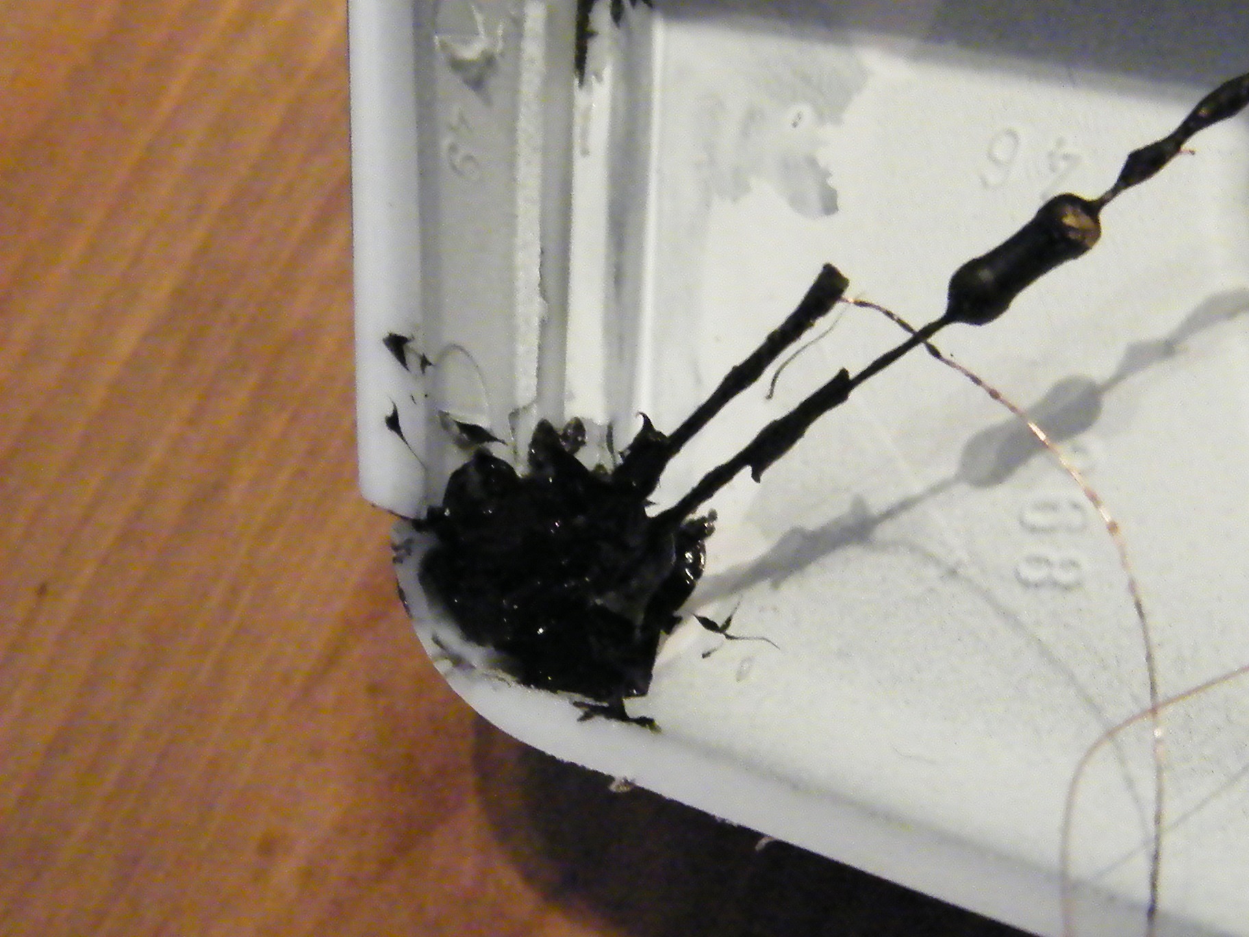
While the CA was settling, I mixed up a tiny little bit of Milliput and rolled some teensy little ropes of it, which I then pressed into the gaps of the forward bussard collectors ahead of the warp crystal (see the fuzzy photo – sorry for the crap focus, didn’t realize it was unclear at the time). This will both reinforce the part in its place, and will also light-block the gap here. The side that isn’t covered by putty (when I put the two halves together) will probably have a gap or two there too, but I’ll rely on some liquid PVA glue or something to fill and then paint over it with black & white.
Once the putty was in, I glued the warp crystal (which was on the same circuit as the strips) into place with CA. I then fixed the wiring in place with a little masking tape to hold it out of the way.

Raytheons – you can see the bends in the legs here (this is after hot-gluing on the outboard, the inboard isn’t fixed yet).
The Raytheons were next. Outboard sides first, I used some flat-face pliers to put two 90-degree (approximately) bends in the legs of the Raytheons, about 3mm apart. This way I could glue the legs flat to the wall and the light would be raised a little off the surface and spread its glow around a bit. I’m still going to get a small ‘hot spot’ I think, but it shouldn’t be too bad. CA and a little blitz of Zip-Kicker and it’s done. Masking tape to hold the wires in place.
Both the Raytheons and the floods are on the same circuit, but they won’t have the same leads since they are on opposite ends of the nacelle. I did make the leads a little too short between where they join and the lights, which meant that the two nacelle halves needed to be very close to each other while I worked these double-lights in. In hindsight I should have given something closer to 15cm of magnet wire lead on these, instead of the 10cm I originally went with. Leave the inboard loose (or fix it with masking tape to keep it from wandering) while you do the rest.

Horizontal thruster fin leaves plenty of room for the endcap and vertical.
After the Raytheon outboard was dry it was time to attach the thruster fin – you can do this before the vertical fin without any trouble, the vertical will slide in under it without too much hassle when the two halves are together (don’t do the vertical first here, it might inhibit a more clean mating of the two halves). Run the wire through the extra hole drilled and glue the fin in place. Both of my fins needed sanding with rough grit to thin them down enough to fit in their trenches, since I’d painted them multiple times (and the light in one of them turned out to have been thick enough to distend the middle of the fin a bit). There’s about 1.5 to 2mm of depth on the trench the fin goes into, so sanding these down to fit was an easy matter, and they went in without too much trouble. Glued with standard model glue to fix in place, bit of masking tape to hold the wires out of the way, done.
While it was drying in place, rather than hold it there with my hands I used a few modeling clamps to park it and went to do some other stuff for a while. Clamps are absolutely great tools, as simple as they are, they really save me a lot of boring manual steps.

Holding the thruster fin in place while it dries with a couple of clamps.

View from the exterior side.
At this point, all the wiring is falling into roughly the same places along the bottom of the engine part, so the natural thing is to start gluing them into place (see the image at the beginning of this post). I started by testing the in-place wiring with a 9V battery to make sure nothing was askew, then removing the masking tape while, holding the wiring in place, and replacing the multiple pieces of masking tape with a single application of CA glue. Some Zip-Kicker to make sure it cured fast, and then some polymer all-purpose glue a little bit offset from it.

Light-blocking “bulkhead” separating the warp grilles from the rear Raytheons.
Next I cut down a couple of oval sections of styrene to block off the back of the engines from the warp strips. Since the Raytheon lights in the back won’t be chained to the same circuit as the warps, if the model is on “impulse” mode then there’s a good chance that without a blocker the bright-white of those two LEDs will bleed through the interior grilles. So a couple of ‘bulkheads’ fixes that problem right away. I painted both bulkheads black and then silver on one side to make sure they did the job right. They won’t fit perfectly, but they will block enough light that I suspect the Raytheons won’t shine through.
The tower LEDs for the forward-facing floodlamps were next. The holes in the nacelles were just slightly tight, so I loosened them up with a needle sander (basically a round stick of plastic textured on the outside with 600-grit) until they could fit easily. Push these lights through until they extend out of the face, and then use a fingertip to press them back into the hole, and then CA with a spritz of Zip-Kicker to fix them in place. After the CA dried I hit it with a little all-purpose polymer glue, and while I had the tube open, I then dabbed some on the warp strips every few centimeters, a little on the warp crystal, and a little on the Raytheons’ legs.

The hole for the forward floods – made to take a clear part from the kit, we’re subbing in tower LEDs.

First push the LED through the hole…

…then use a finger to push it back in flush before securing with glue.
These lights now had both CA and polymer glue, so I’m double-covered against whichever one ages out first. I then fired up the hot glue gun, and put a glob wherever it seemed like a light could use it – dabs all along the warp strips, a plop on the Raytheon, a plop on the tower LED. Dabs of it along the wiring to give them a third type of glue to hold them in place.
To guarantee that the floodlights wouldn’t overspill into the interior, I then used Black Seal all over it to completely cover it and prevent light leakage.
Black Seal is a very fluid gel out of the tube, so it’s hard to be clean with it. It looks like crap here, but it does the job.
At this point, the only thing left was to fix the second Raytheon and tower LED on the inboard side, and to attach the diffuser shield I’d made over the warp strips (basically a piece of clear styrene cut to size and sprayed with dull-coat). In went the two inboard lights (same process as the outboards – CA, then polymer glue, then hot-glue, and finally Black Seal on the tower). On went the diffuser, then I ran all the pairs of leads from the various wiring harnesses through the hole that would take the engine pylon. Then a fast dry-fit to make sure everything went in right. This was really useful, since it helped me spot which wires needed attention to keep them from getting caught between the two halves when putting them together.

Diffuser over the warp strips, and second tower LED in and blocked…only the outboard Raytheon remains.
Tested the wiring with a 9V battery again here, just to be sure.
After about an hour to let the Black Seal get a skin, letting the last Zip Kicker and other glues dry up, it was time to seal the whole thing up. Fixing the two halves meant applying polystyrene model glue around the seam, and into the receiving holes for the stabilizing posts. I try never to put glue on the posts themselves, because it’s too easy to brush them against something while jockeying the parts into place and get glue on something that doesn’t like it. Because of their length and the thin metal applicator, this meant that some of the glue was already getting tacky by the time I came around and finished making sure the whole seam got a line of it. I put a little extra on these areas and then pushed the two together, being careful to make sure no wires escaped from the wrong place.

The halves fit reasonably well, but you can see there are definite gaps to be dealt with later when we get to the putty/sanding stages.
Once the parts were together, to make sure no spread of them while the glue dried I used various modeling clamps and vices (sets of these are available on eBay for under ten bucks) to hold the halves together and just let it sit for the glue to cure for a couple of hours. For reference, those are 5-inch (25cm) clamps. A note on these clamps – most of them are damned cheap for a reason. I used to have six of these big ones, but the pressure of the spring has broken three of them in the past year. It’s a bit of a heart-stopper when that happens, but it seems generally not harmful to the model itself. Just check the space where it was, and attach a new one or a vice to the spot. Regardless, a set of clamps are really super-useful when doing builds like this.

Clamps attached – helps to reduce gaps, and saves your hands a lot of cramping.
When I returned, the glue had dried nicely, leaving a noticeable but very manageable seam on the parts. I tested the electrics again to make sure nothing went wrong, and then got to work filling the pylon space. When it attaches, the pylon will have three posts that fit into the nacelle, and there’s a wide hole to accommodate part of the pylon there too.

Cotton wadding, Black Seal, and a little acrylic paint to fill the big gap here and light-block the assembly.
I’ve seen Boyd at TrekWorks use black seal to fill this entirely, but I’m not such a
giant fan of that. I feel it’ll be a little too easy to get too messy with it, despite its easy wipe-off nature. Instead, I did some black seal, and then a big hunk of cotton wadding (the stuff in the makeup section of the drugstore, comes in a long package and you just rip off a hunk of the size you need) got pressed up into the gap there. Once I was sure that stuff would stay put I hit it with some black acrylic paint mixed 50/50 with water and left it to dry. The reason for this is to light-block the hole, preventing the warp strips from bleeding blue light into the pylon. Wouldn’t be good to have the pylon glowing blue from inside.
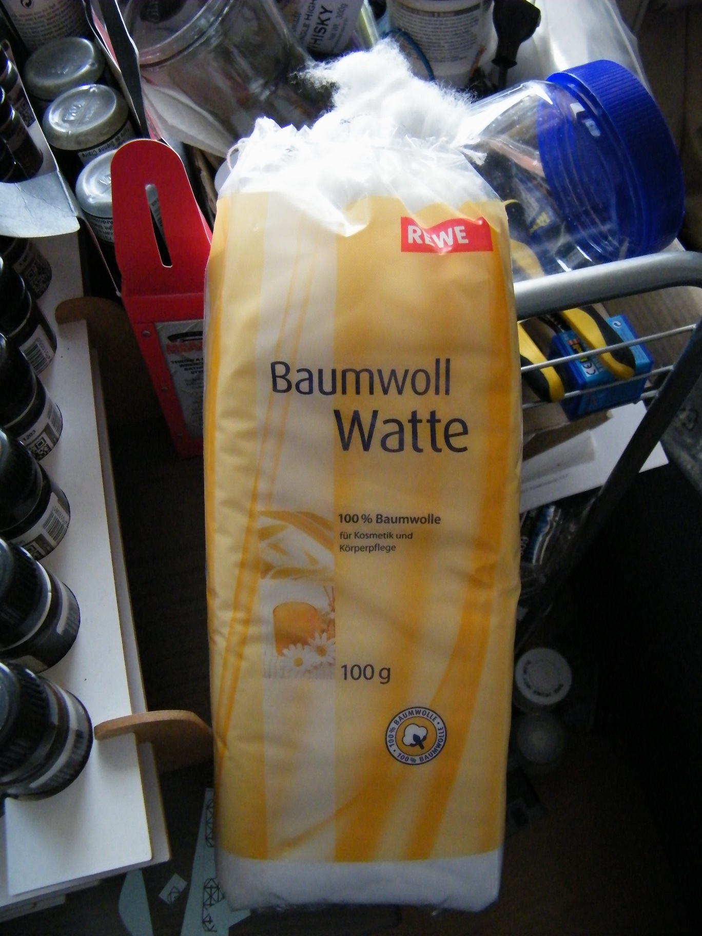
Generic cotton wadding, used for removing makeup and such.

Paragrafix endcap installed – fits like a glove.
After the gap was filled to satisfaction, I primed and attached the photo-etch endcaps for the engines. These replace the plastic parts completely and fit almost flush if you have managed to keep them flat. A line of CA glue on them and they slid right into perfect position with only a tiny seam around the edge. Then, an application of glue to the plastic showing, and I slid the vertical fin into place where it was received with a satisfying ‘snap.’ Left it to dry a while, and ta-da! Engine nacelles assembled!

Vertical slides right in and sits perfectly (sorry about the out-of-focus there).

A bit of clear gloss on the exposed LED surface will prep it for masking fluid and protect it from the sanding stage.
As a prep for the sanding effort to come, I applied a big dab of gloss clear acrylic to the forward floods and the rear anti-collision strobe. This dries to a hard bump on the strobe and fills in around the cracks of the floods. I’ll be putting a liquid latex mask (Humbrol “Maskol”) on these, and the gloss coat will prevent it from sinking into spots where it couldn’t be removed. As well, it also makes it really easy to remove the mask when it’s no longer needed. I’ll use regular masking tape on the warp crystal and various grilles. I’ve applied gloss coat to the thruster ports, and while the top and bottom took that without a sweat, the sides and rears pulled the clear-coat in and left me with a hole again. I’ll figure something out there later.

The gap you see here is before gluing – it’s much reduced after gluing, but still pretty obvious. Needs some work.
Next go-round I’ll be working with putty and sanders to clean up the few Black Seal stains that remain, eliminate all the seams and sand them down to nothing. Then a re-application of white and perhaps some cleanup of the inner grilles. There are some pretty serious ga
ps (between the horizontal fin and the rear of the engine, for example) and a few very subtle ones (where I might get away with clear coat paint or something to fill), so that’s going to be a separate post of its own.
These engines are the first really “recognizable” part of the ship which you’d know to look at when seeing it from the outside – the other interior parts were fun, but in all honesty they felt like they could be part of any ship. With these engines done, I can look at them and see now that what I’m making is really going to be the Enterprise. Feels good to see her start to take form here.

It really is going to be the Enterprise!
See you next time!

Pingback: The USS Enterprise (Refit) from Star Trek: The Motion Picture | Borked Code
Pingback: The USS Enterprise (Refit) from Star Trek: The Motion Picture | Borked Code
Discovered your story from a search and wow – great work! I’m looking around to see if anyone has come up with some small, light device that will be able to focus a beam from the nacelle to light up the registry on the secondary hull vs some big light spray and/or solving through raytheon effect. Did you consider anything like that?
On the facebook group “1/350 Enterprise Build” I have seen people using tiny pin-lights on the opposite nacelle that end up focused perfectly on the opposite nacelle in just the right place. Don’t ask me how that was aimed properly, but I imagine a lot of swearing and blood, perhaps an animal sacrifice to Satan, was involved. Same person did set up what looked to be a tower light that illuminated the sides of the secondary hull as well. Again, probably involved a contract with C’Thulhu to get that one done. Since mine will be affixed to a solid base and not really move, I’ve concluded that I’ll use some small spotlights from the base to get some of that done. Unfortunately I’ve been stalled for a while, trying to assess how to get the base done with a big dust cover. I live in Germany but I’m not native here, so finding complicated solutions like that is a lot tougher because I don’t have the language skills to describe what I need very well.